EWS
Documentation Download: MCU GmbH & Co. KG
Am Gehrenbach 8
D-88167 Maierhöfen
Phone: +49 (0) 8383-92233-10
E-mail: info@mcu-gmbh.de
Web: www.mcu-gmbh.de
wiki.mcu-gmbh.de/en/docs/ews/
PIN: 9765EWS FLEX BOX 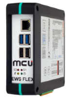
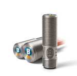
EWS COP BOX 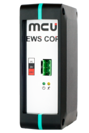

This manual is exclusively meant for technical staff familiar with the applicable national standards. The following explanations and notes must be complied with when installing and starting up Toolinspect.
Read this manual before putting Toolinspect into operation.
Keep this manual accessible to all users for future reference.
The technical staff has to make sure that the application and use of the products described here meet all safety requirements, including those of all applicable laws, regulations, provisions and standards.
This documentation has been drafted with due care. However, the product described therein is subject to continual further development.
Therefore, this document is not to be considered conclusive for each and every case regarding its compliance with the specified performance data, standards or other characteristics and does not represent assurance of properties in line with § 459, Section 2 of German Civil Code. We reserve the right to change this document at any time and without prior notice if it contains any technical errors or typos. No legal claims can be made regarding changes to products already delivered based on the information, illustrations and descriptions in this document.
© This manual is protected by copyright. It must not be made available to a third party in whole or partly without the explicit written consent of the company MCU GmbH & Co. KG.
- This manual contains information and instructions on the proper use of the products.
- The products described here have been developed, manufactured, tested and documented in compliance with safety standards. This product does not pose any risk to persons or property if used in compliance with the handling and safety instructions specified for its planning, assembly and proper operation.
- The following EU directives were applied:
2014/30/EU (EMV-Richtlinie)
2011/65/EU bzw. 2015/863/EU (RoHS-Richtline)
The following standards were applied:
DIN EN 61000-6-2:2005
DIN EN 61000-6-4:2007
DIN EN 61010-1:2010 + A1:2019 + A1:2019/AC:2019
The device is not prone to wear and tear. Therefore, specific values for MTTFd or B10d cannot be indicated.
The device is intended for use in an industrial environment (emission class A).
This is a class A system. Using it in residential areas can lead to radio interference; in which case one cannot demand from the operator of the system to take proper measures, or hold them liable for costs.
This product will run safely and without a flaw provided that it is transported, stored, setup, assembled and operated properly.
The technical staff has to ensure that the application and use of the products described here meet all safety requirements, including those of all applicable laws, regulations, provisions and standards.
Explanation of the safety symbols
This manual contains the following safety symbols. They are especially meant to draw the reader's attention to the safety instruction text alongside the symbols.
 Caution
This symbol is used to make you aware of risks for the machine, material or environment.
 Note
This symbol refers to information that can give you more insight.
Qualified personnel
The requirements expected from qualified staff comply with profiles described by ZVEI (German Electrical and Electronic Manufacturers' Association) and VDMA (German Engineering Association).
Adjustments or modifications to our products' hardware and software, if not clearly specified in this manual, must only be carried out by the technical staff of the company MCU GmbH & Co. KG.
Tampering of unqualified persons with the hardware or software, or ignoring the warnings as specified in this manual or on the product itself, can lead to severe personal injuries or damages to property.
Only qualified persons in compliance with IEV 826-09-01 (modified), who are familiar with the contents of this manual, should be allowed to install the described products or do maintenance work on them.
These are individuals, who
- based on their technical education, know-how and experience, as well as their knowledge of relevant standards can assess the work that needs to be done and can recognize the possible risks involved.
- based on having worked for several years in a comparable area have a level of know-how similar to that accrued through a technical training.
Based on the purpose of its application, the product is delivered with a certain hardware and software configuration. Modifications to the hardware or software configuration, which go beyond the options as documented, are not permissible and will lead to non-liability of the company MCU GmbH & Co. KG.
The EWS FLEX BOX device uses sensors to detect collisions, monitor machining processes, and read and evaluate data from PLCs or CNC controllers.
The EWS COP device is designed to prevent collisions caused by incorrect input of correction data or errors when re-entering the NC program.
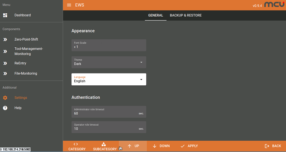
To configure the TCP/IPv4 address of the EWS box, create a file named ip_adr.txt in the root directory of a USB stick. The file must contain a valid IPv4 string, for example: 192.168.214.210
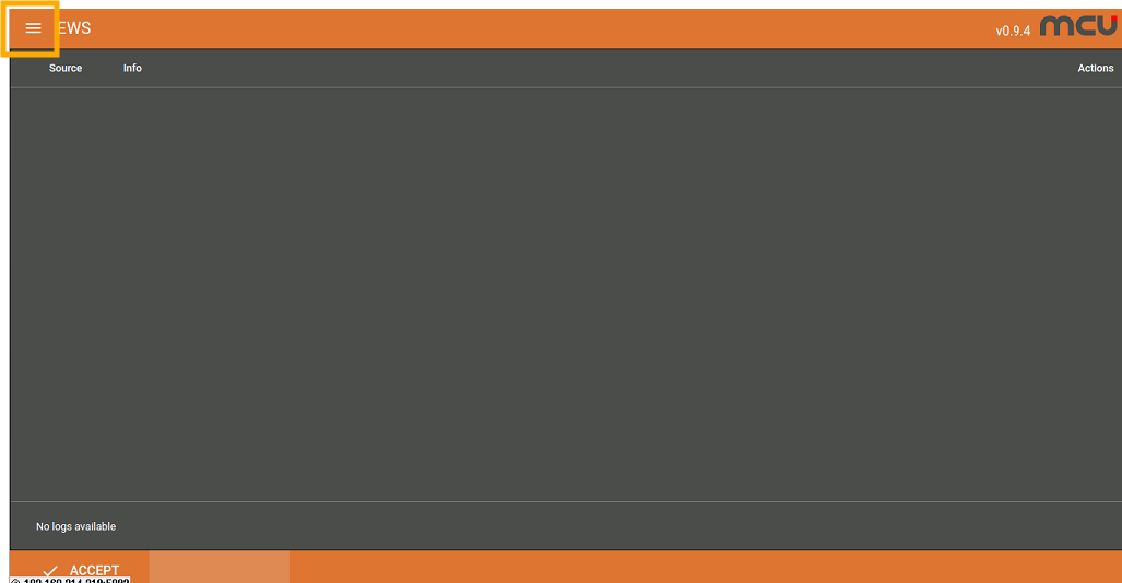
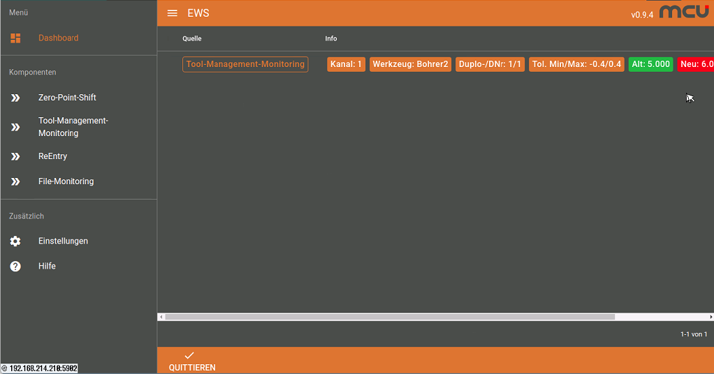
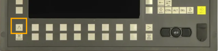
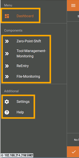
This function monitors changes made in the zero point offset tables.
The permissible limit values are generally predefined in the system via a specified value. However, these defined values can be individually adjusted at any time via the EWS application.
Monitoring begins, due to system design, after exiting the zero point offset table in the Siemens HMI.
If the zero point offset is changed during machine operation, an axis position range can be defined in the system within which the machine stop triggered by the alarm message will be executed. For example, this can prevent the machine from stopping during a machining process. The axis position range is defined during commissioning via NodeRed.
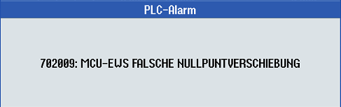
Alarm message in the NC control system:
Alarm message in the GUI:
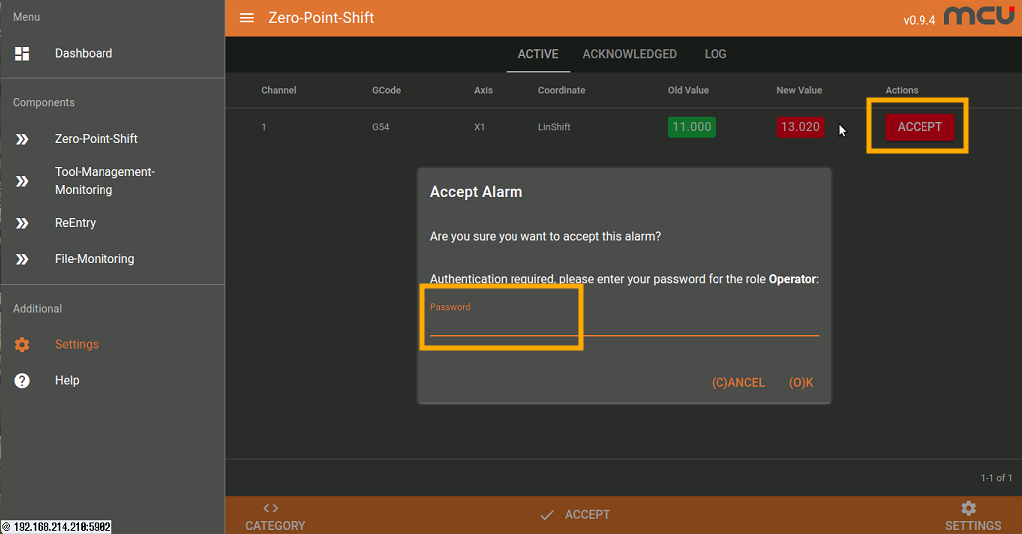
In principle, alarm messages can be "accepted" either by correcting the value in the zero point offset table of the control system or by entering the password: VISA. By acknowledging the alarm, the new zero point offset value becomes valid.
The tolerance limits for individual zero point offsets can be manually adjusted via the "Settings" button.
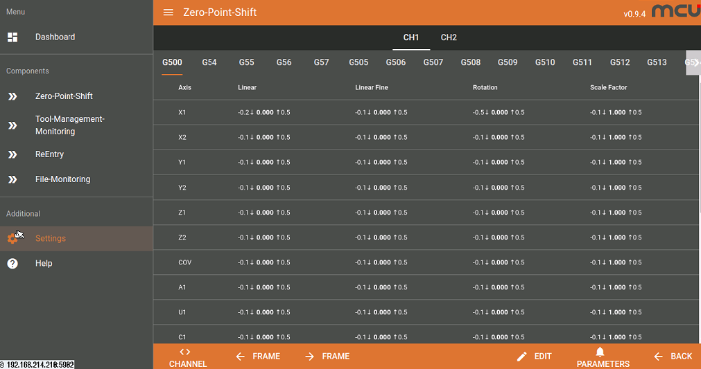
Edit:
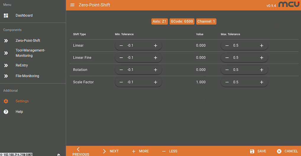
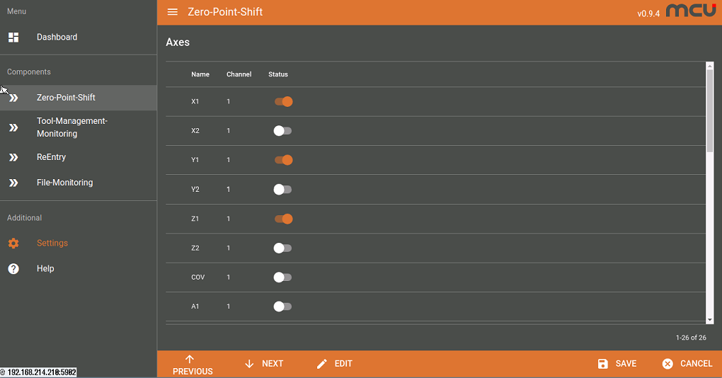
Via the "Parameter" button, you can select which axes should be included in the monitoring process:

Here is an example in which the X, Y, and Z axes have been selected:
This function is used to monitor changes in the tool table.
The permissible limit values are generally predefined by a system-defined setting. However, these values can be individually adjusted at any time via the EWS application.
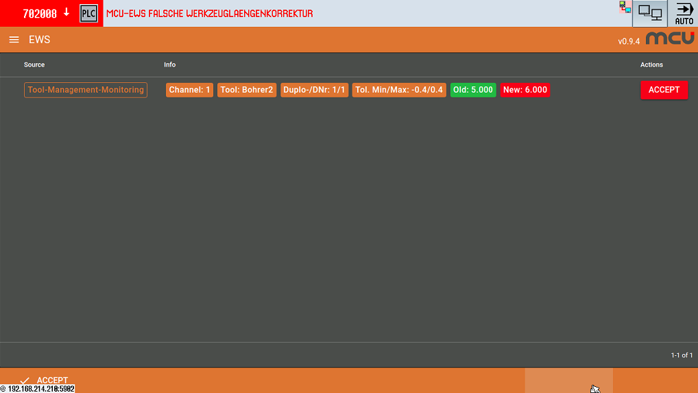
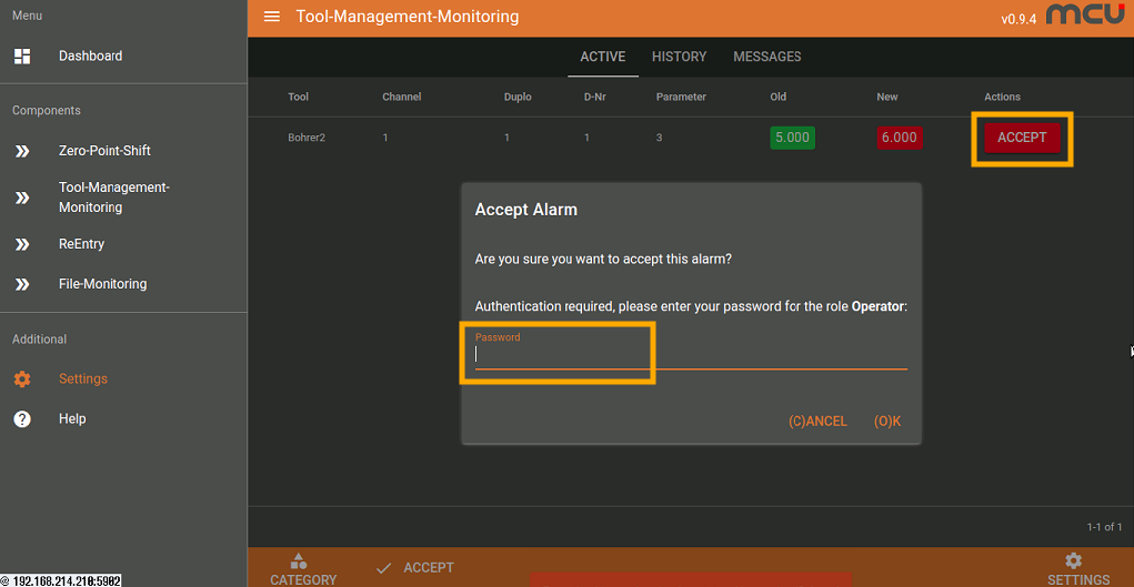
In principle, alarm messages can be "accepted" either by correcting the value in the tool table of the control system or by entering the password: VISA. By acknowledging the alarm, the new tool correction value becomes valid.
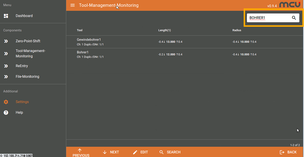
In the search window, the tool can be searched by its designation. Here, for example: "Bohrer".
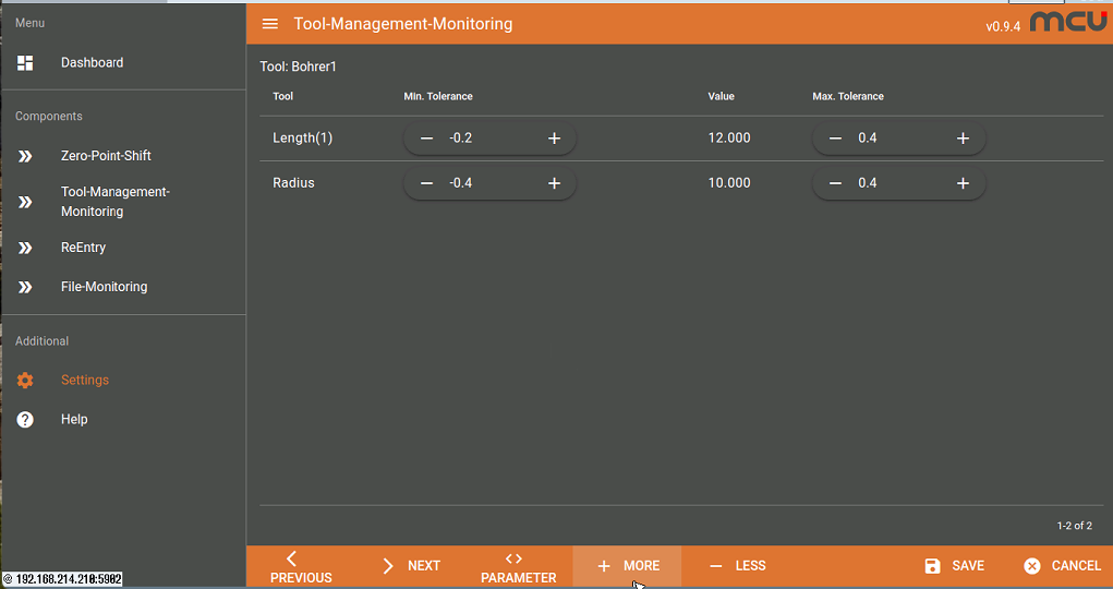
By pressing the "Edit" button, the tolerance value can be adjusted:
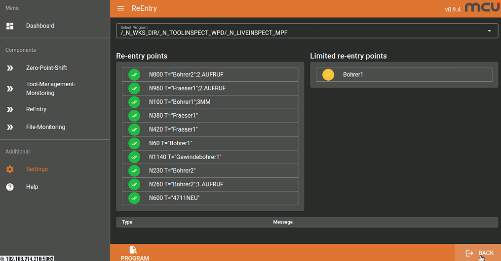
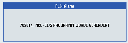
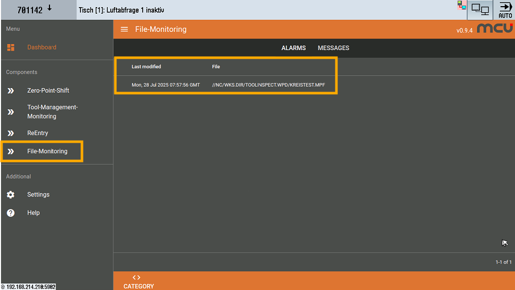
General
The ews backup and restore process of a EWS device is done with an external USB flash drive, preferable up to 1 GB of free memory.
For all following sections the event files should be created in the root directory of the USB flash drive.
Step 1
Create a file named
ews_make_backup.txt
one an USB flash drive, in its root directory.
Step 2
Insert the USB flash drive in one of the free USB ports of the EWS.
Step 3
The EWS light will go off. Wait until the light returns to its normal blinking. Then pull the flash drive.
Step 4
Open the flash drive on any computer. Check if there is a folder called "ews_backup".
The ews_make_backup.txt should be renamed with the prefix "_failed" or "_success". Which indicates the outcome of the backup.
For futher diagnostics open the ews_make_backup.txt... file with a TextEditor.
Copy the folder
ews_backup
to a USB flash drive. This folder can contain one ore more backups.
The backups are zipped files named by date.
Create a file called
ews_restore_latest.txt
on the USB flash drive.
Optional replace "latest" by the exact date of a backup in your ews_backup folder, in case you want to restore a different backup then latest one.
Insert the USB flash drive into the EWS and wait until the LED blinks again, then pull the stick.
To check if the restore was successfull open the USB flash drive and check the prefix of the ews_restore_latest.txt for "_success" or "_failed".
For more details open this file with a TextEditor.